

What is DMX? I ask this question to every person I interview for a job. It’s an important question because while the lighting industry is using ethernet-based communication in certain situations, DMX will still be around for a very long time.
DMX is not something we think a whole lot about, but we use it extensively in the lighting world to control dimmers, moving lights, and some special effects. For something that has a big impact on what we do, it seems few people know how DMX communicates from control desk to dimmers/fixtures. It is a very robust system that can travel long distances compared to newer systems and has proven to be incredibly reliable.
So what is DMX, and how does it communicate from console to device?
A little bit of history first. DMX is a digital system that was devised in the 1980s. Previous systems were analog. The most common method of control was a 0 to 10-volt control line that was connected via cinch-jones connectors. Every dimmer had its own 0 to 10-volt line, so if you had 42 dimmers, you would have 42 conductors plus commons from the console to the dimmer room. The conductors were usually bundled in groups of six. It would take 7 control cables to control the 42 dimmers mentioned above.
The other thing about a 0 to 10-volt control was the issue of voltage drop. Over long runs, a significant amount of voltage would be lost to resistance. Because of voltage drop, the dimmers had to have their trim set so that whatever voltage made it to the dimmer racks when the console was at 100% could be trimmed so that the dimmer was at 100% as well. For example, there may have been only seven volts at the rack by the time it travelled down the control cable; therefore, you would need to trim your dimmers so seven volts was equivalent to 100 percent. If you had a bad cable and needed to change it, you would need to re-trim the racks to which the new cable was connected.
For these reasons, and the need to have an industry standard for communicating between consoles and dimmer racks of different manufacturers, DMX 512 was created.
DMX 512 was first created by the United States Institute for Theatre Technology (USITT) in 1986. USITT maintained the standard until 1998 when it was transferred to the Entertainment Services and Technology Association (ESTA). ESTA then started the revision process needed to make it an American National Standards Institute (ANSI) standard, which was approved in 2004. It was officially called the “Entertainment Technology—USITT DMX512-A—Asynchronous Serial Digital Data Transmission Standard for Controlling Lighting Equipment and Accessories”. It was again revised in 2008 and is the current standard, known as “E1.11 – 2008, USITT DMX512-A”, or just “DMX512-A”.
*In 2011, ESTA merged with the Professional Lighting and Sound Association (PLASA), but split back into separate entities five years later. ESTA continues to maintain the DMX 512 standard which has been reaffirmed in May of 2018. It can be downloaded for free from the ESTA Technical Standards Program.
DMX is an acronym for Digital Multiplex. 512 refers to the number of control channels a single “universe” of DMX can communicate. In the 1980s, the idea of needing more than 512 control channels was incomprehensible. As the years progressed, the introduction of moving lights that use multiple channels became common. Multiple runs of DMX became necessary to accommodate the new technology and the term “universe” came into existence to delineate multiple, unique runs of DMX.
So what do we mean by “multiplex”? Simply put, DMX 512 is a serial connection that feeds data one bit at a time down the cable. It sends channel one, followed by two, then three, all the way to channel 512, and then starts all over again constantly looping through all 512 channels as long as the console is sending control. At any instant, you will only see a piece of a single channel. Unlike analog signals of the past, the information for each channel is sent digitally as an 8-bit binary number. The number range is from 00000000 (0 in decimal) to 11111111 (255 in decimal). Consoles will often interpolate the decimal range (0-255) to percent (0% to FL). Regardless of how the console is presenting the information to the operator, the console is sending a number between zero and 255 for each channel.
How does DMX do this? It uses the RS-485 (EIA-485) electrical standard for drivers and receivers, which dictates the kind of hardware used to communicate. This standard allows for cable runs of 4000 feet, although most manufacturers of DMX equipment recommend runs of no more than 1000 feet before a repeater is added to regenerate the signal.
A maximum of 32 devices can be daisy-chained together in a single DMX chain with no more than 300 feet between devices and a terminator added at the end of the run.
A DMX packet usually consists of 512 channels, known as Channel Data slots (CD), multiple time marks, a start code, and a break. I will start with the smallest piece, the bit, and build up to the full DMX packet.
As mentioned, the information is being sent digitally, so it consists of a pulse waveform with highs (+volt) and lows (-volt) which are equivalent to 1s and 0s in binary number notation. For this to work, all devices need to be looking at the waveform generated with the right timing. The DMX 512 standard calls for a 250 kiloHertz transmission rate. This means that 250,000 bits of data can be transmitted every second. Dividing one second by 250,000 means that each pulse of the DMX wave is 0.000004 of a second long, or four microseconds expressed as 4µs.
For the console to send out a data bit equal to 1, it would send positive voltage down the DMX cable for 4µs. Conversely, for it to send a 0, it would send negative voltage for 4µs. To send a single 8-bit number down the line, it would require 32µs because each of those 8 bits requires 4µs to transmit. Eight bits represents one DMX channel, but we need 11 bits of data to make it a valid DMX CD slot. The DMX CD slot should always be 44µs long (11 bits x 4µs). The other 3 bits are needed as start and stop bits to mark the beginning and end of the 8-bit value. The DMX standard calls for one start bit (set to 0) before sending the 8-bit channel value, and two stop bits (set to 1) to mark the end of the 8-bit value. In figure 1, the DMX data signal was attached to an oscilloscope. The beginning and end of the DMX CD slot were marked with start (S) and stop (P) bits as well as the 8 bit value sent in between.
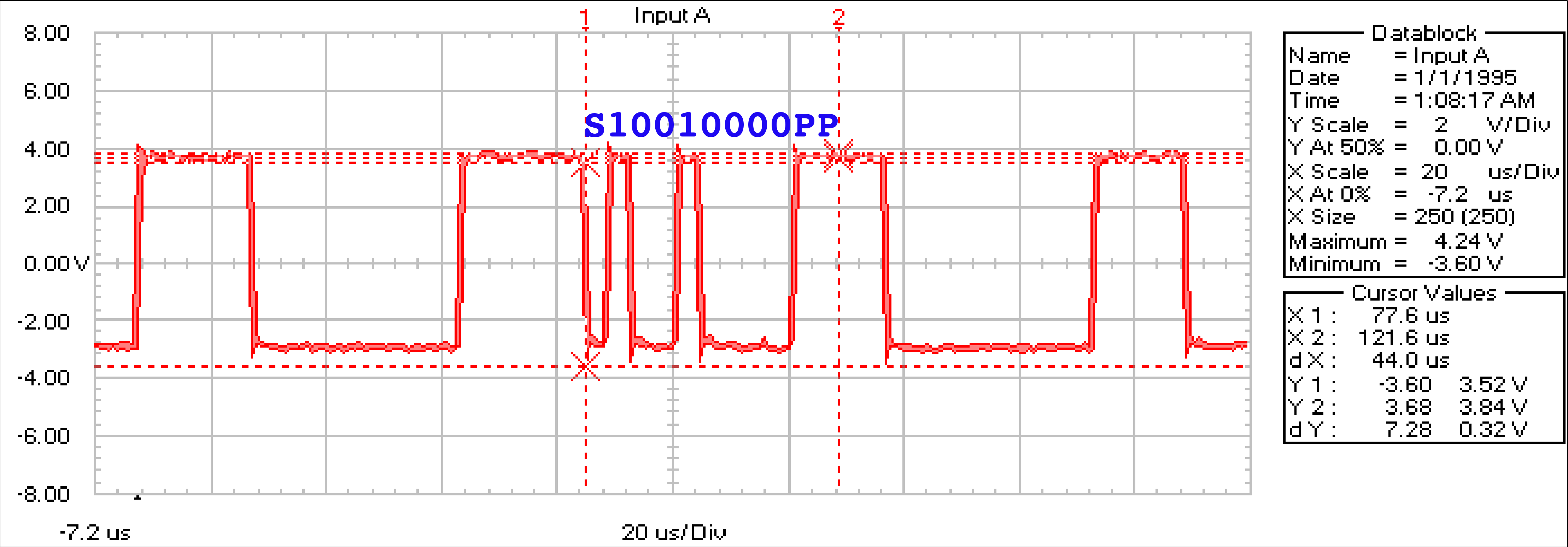
So we have our DMX CD slot with 1 channel of information. It has one start bit, an eight digit, binary number, and two stop bits. How do we read the binary number for the channel value? In the case of transmitting DMX and viewing the waveform on the oscilloscope, we read the digits from left to right with the left most digit the least significant digit, doubling in value as we move to the right. Each, next digit’s value is double the previous digit. The first digit has a value of 1, the next 2, the next 4, upward to the 8th digit with has a value of 128. Figure 2 is animated with one channel displaying each bit in a DMX CD slot and the associated decimal value in red.
For figure 1, we have a DMX value of 10010000. The first digit has a value of 1 and the fourth digit has a value of 8. We ignore the rest because they are set low. Add the two values up and we know that the DMX value is 9 for that CD slot.
So we have one DMX CD slot constructed. How do we do the rest? Things get pretty simple at this point. We know that each DMX CD slot is 11 bits of data and take up 44µs of time. In between each DMX CD slot is Mark Time Between Frames (designated as MTBF). According to the DMX 512 standard, the MTBF is set to high (1) and can be from zero to 250 kilobits long, or zero to one second long. Each manufacturer can decide how long they would like to make the MTBF. In the examples supplied, the manufacturer has decided to go with a 2 bit MTBF which comes out to 8µs. The MTBF is placed before each DMX CD slot transmitted.
At the end of the last DMX CD slot, a Mark Time Between Packets (MTBP) is placed to mark the end of the entire DMX packet and to start over at the beginning. The MTBP is also set to high and can be from zero to 250 kilobits or zero to one second long. This end of packet does not necessarily need to be placed after the full 512 channels have been transmitted. It could be done anytime the manufacturer decides. You may come across older lighting desks that only transmit 128 DMX CD slots from the console. In a case like that, the MTBP was placed after the 128th CD slot and the packet starts over. The console doesn’t bother transmitting the other 384 CD slots that are possible.
The MTBP marks the end of the DMX packet and the majority of the work has been done. There is just a little more information we need to cover at the beginning to have a full DMX packet described.
At the very beginning of a DMX packet is a section called the break. The break will be set low and remain low longer than any other element of the DMX packet. According to the DMX 512 standard, the minimum amount of time the break can be is 92µs for the transmitter (88µs for receivers). It can be as long as one second. The next longest time there can be a low value is 36µs, which is any CD slot with a value of zero (1 low stop bit and the 8-bit value set to 0. 9 bits x 4µs = 36µs). When any device on the DMX chain sees the data line low for at least 88µs, it knows it has hit the beginning of a new DMX packet. Figure 3 shows the break on the oscilloscope. The measurement of the break from this manufacturer is 120µs (30 bits), so there is no mistaking when the break has been encountered.
After the break is a Mark After Break (MAB) which is set to high for a minimum of 12µs for the transmitter (8µs for receivers) to a maximum of 250 kbits. This manufacturer uses a MAB of 12µs on their waveform. Like the MTBP, there is only one MAB in each DMX packet.
Finally, after the MAB, and before the first DMX CD slot, there is the Start Code (SC). For decades the Start Code was exactly like a DMX CD slot but with the number value set to zero. It was often called dimmer 0. It is 11 bits long, has a start bit set at zero, an 8-bit binary number set to zero, and two stop bits set to 1. It is 44µs long.
As of the most recent writing of the DMX 512 standard, the Start Code can now be used for enhanced functionality. This is typically used for bidirectional communication, like RDM (Remote Device Management), where alternate start codes can be sent out to newer equipment. These codes can query the equipment for setup, change settings within the equipment, etc. Since RDM is a fairly recent development in DMX, not all equipment is compatible with the standard and care must be taken when building a DMX network if the intention is to use RDM.
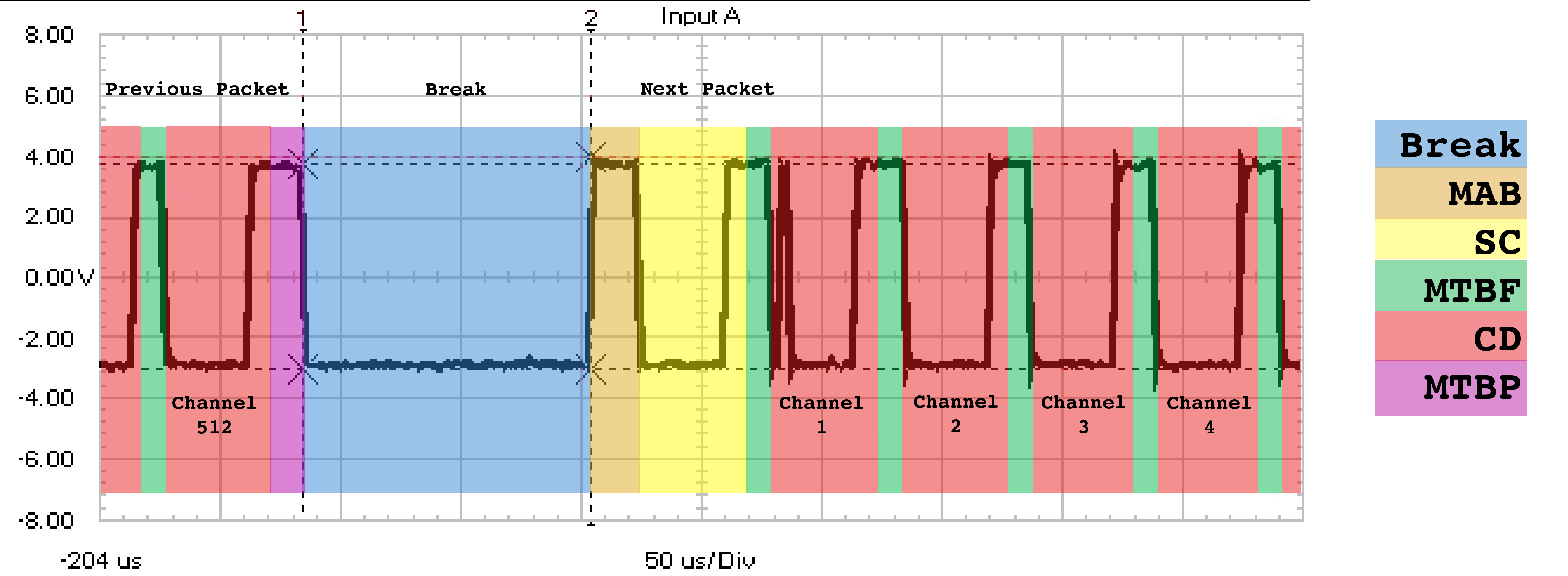
Figure 4 shows the entire construction of a DMX packet with the different pieces overlaid in color. You will notice that there is no transmission of what channel number is being sent. After the Start Code, all devices count slots starting from 1, and work their way up to the next break. Once a device counts up to its address, it knows that channel data is intended for it and processes the data.
The standard connector for using DMX is the XLR 5-pin connector. All other XLR connectors are out of specification. Also, the XLR is wired ‘the right way around’, in that connectors carrying data (live) are always female, and connectors receiving data (load) are always male. While 5-pin is the standard, many manufacturers have opted to use the 3-pin XLR connector. Since the 5-pin is carrying two data pairs and most installations are only using one, 3-pin connectors don’t usually cause any problems …except when they do.
There is the issue of mismatched connectors that cause people to stock cable in both flavors or, at the very least, have adapters ready to make them work. Another issue is concerning cabling. Some people will choose to use mic cable when connecting devices in a DMX network with 3-pin connectors. This may or may not work within the network. The electrical characteristics of DMX require the cable to have an impedance of 120Ω (±20%). Mic cable has no such requirement and can range wildly from 25Ω to well over 200Ω. This could cause data reflections in the cable large enough to obliterate the original data signal. Many long, frustrating hours can be spent troubleshooting a control issue only to discover that incorrect cable was used to connect devices.
Data reflection can also happen if the end of the DMX line is not terminated. A DMX terminator is made from a male 5-pin XLR connector. It is simply a 120Ω resistor connected across the data lines at the last device in the daisy chain. The terminator will give the characteristics of an infinitely long 120Ω cable, eliminating any data signal reflections.
Lighting technicians come across DMX every day. It is a reliable, robust method of communicating between consoles, dimmers, moving lights, and special effects. That said, it is not perfect. Knowing how DMX communicates between devices will help you when things don’t go as planned. You may be working with an old device that doesn’t quite fit the current standard, or you might come across a new, cutting-edge piece of gear that has to do something outside the DMX 512 specification to work correctly. Knowing how devices are supposed to communicate will help you troubleshoot these issues when they occur.
With the implementation of RDM, DMX should enjoy a long life. There is much more information about DMX than what was covered in this article, so I encourage you to investigate this well-used, but not necessarily well-understood, communication system.
DMX 101: A DMX 512 Handbook by Elation Professional
The DMX512A Handbook: Design and Implementation of DMX Enabled Products and Networks
by James Eade (Entertainment Technology Press, 2013) ISBN 9781904031727
“What is DMX 512?” by Ujjal Kar
Stage Lighting: The Science Of Colour And Light
Losing The Cord: Converting From AC To DC
Join TheatreArtLife to access unlimited articles, our global career center, discussion forums, and professional development resource guide. Your investment will help us continue to ignite connections across the globe in live entertainment and build this community for industry professionals. Learn more about our subscription plans.

Love to write or have something to say? Become a contributor with TheatreArtLife. Join our community of industry leaders working in artistic, creative, and technical roles across the globe. Visit our CONTRIBUTE page to learn more or submit an article.


Michael Cassera enjoys a twenty-seven-year long career with Cirque du Soleil spanning three of their long-running resident shows: Mystère, Zumanity, and LOVE. With Cirque, Michael has worked as a Followspot Operator, a Board Op., an Assistant Head, and Head of Lighting. He is currently the Technical Manager for Mystère. Before joining Cirque, he worked for a brief time as a followspot operator for Siegfried and Roy at The Mirage. Prior to moving to Las Vegas, Michael worked on the bounce off-off-Broadway and in the NYC tri-state area as a stage electrician and lighting designer. He was also employed as a local stagehand at Giants Stadium and Brendan Byrne Arena. A graduate of The School of Visual and Performing Arts at Syracuse University, Michael earned his Bachelor of Fine Arts in Drama with an emphasis in Design in 1991. He continues to live in Las Vegas with his wife, Heather and their two dogs, Maggie and Roxie Li.
Read Full Profile